Bushings & Hubs
Bushings & Hubs for Verified Shaft Interfaces
Taper, XT, split taper and QD mounting families backed by catalogue drawings.
Bushings and hubs may look like simple rings, but the useful selection data lives in the taper, bore, keyway, screw pattern, hub seat and mating component. This site groups the catalogue into practical families so an engineer can move from application to a verifiable series instead of matching by photograph alone.
Start with Taper Bushings, QD Bushings or Split Taper Bushings, then follow the matching hub or adapter path when the assembly requires one.
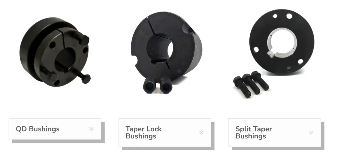
Taper, XT, split taper and QD bushings with matching hubs and adapters.
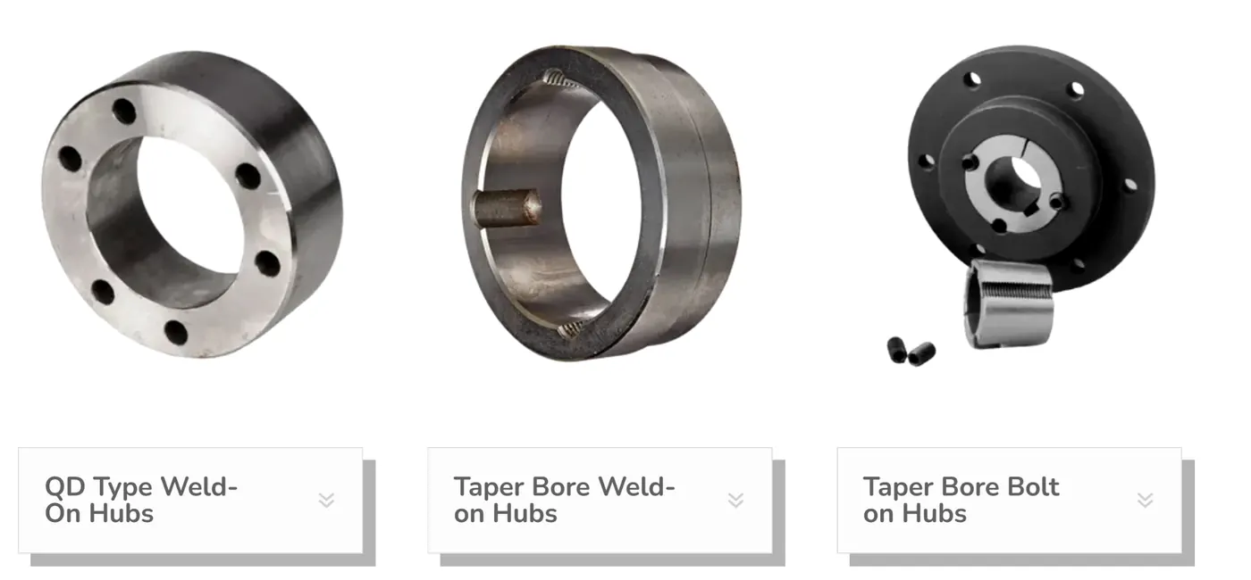
The catalogue includes tapered bushings, quick-detachable QD families, split taper systems, XT bushings, matching hubs, weld-on and bolt-on hubs, and taper-bore adapters. Each product page keeps the model family visible and converts missing operating data into RFQ questions rather than unsupported claims.
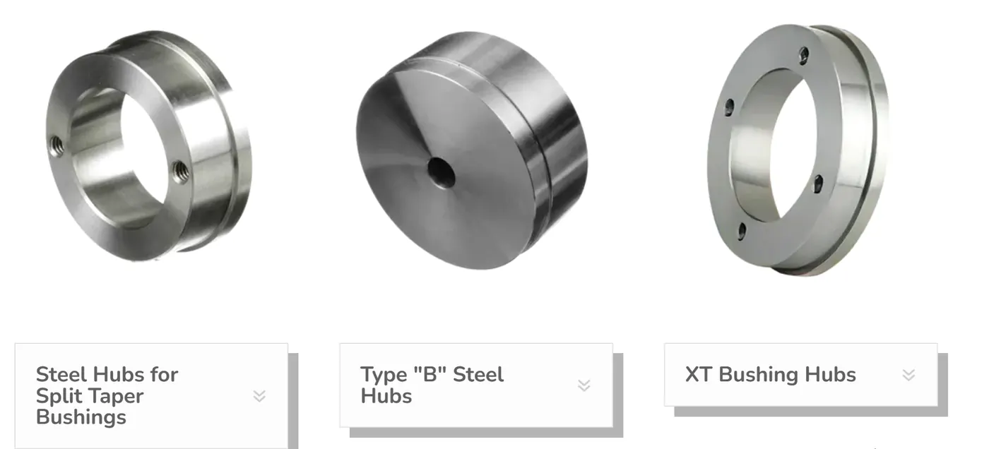
Selection starts with the interface, not with an outside diameter that merely looks similar. Record the shaft size and tolerance, key and keyseat geometry, the bushing or hub series printed on the existing component when available, the mating component geometry, and the assembly direction. Then compare those inputs with the correct series drawing. A taper system that appears close in a photograph can still use a different taper, flange thickness, screw pattern, keyway convention or hub seat.
For replacement work, measure after cleaning the shaft and mating part. Check for fretting, burrs, corrosion, bell-mouthed bores and key damage before assuming that the previous component failed because of the bushing itself. For new equipment, keep the shaft, bushing, hub and mounted element in one drawing stack so concentricity, axial location and service access are considered together.
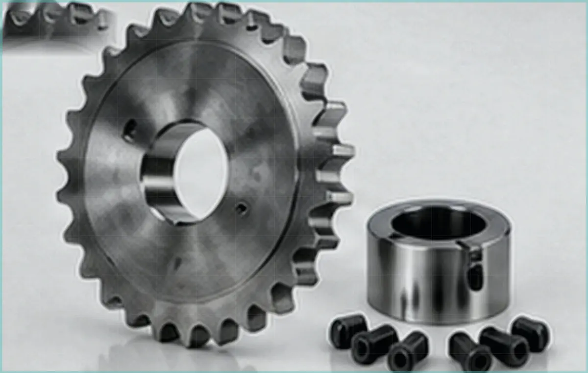
Common use cases include pulleys, sheaves, sprockets, conveyor pulleys, fans, fabricated plates and other rotating components where a removable or modular shaft interface is useful. The correct choice depends on the mating part and duty. A Drive catalogue found during evidence discovery also documents taper-bushed and QD-bushed sprocket configurations, which supports sprockets as an application context without turning a sprocket catalogue into a bushing specification source.
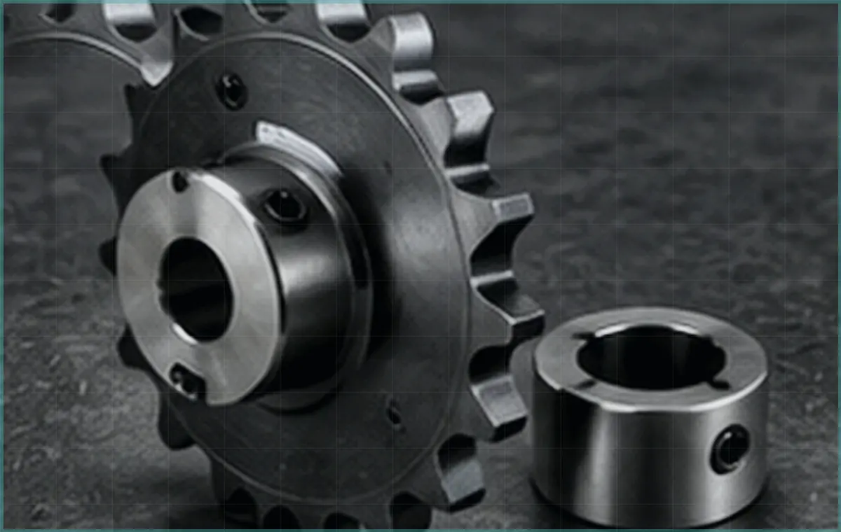
A tapered mounting system uses relative axial movement between mating tapered surfaces to develop radial grip on the shaft and locate the mounted component. The split feature allows controlled contraction as the fasteners are tightened. Exact geometry and screw arrangement vary by family, so the installation sequence and release method must be taken from the selected series.
QD, split taper, XT and conventional taper-bushing families should therefore be treated as distinct systems even when their purpose is similar. The model identifier and mating hub are part of the interface definition.
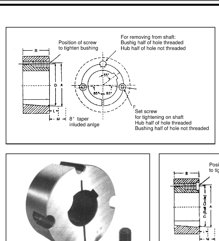
Useful configuration fields include series, shaft bore and tolerance, keyway or key details, mating component, assembly direction, speed, torque or transmitted load, duty cycle, shock, environment, quantity and any required inspection documentation. Where a standard series does not fit, include a drawing so engineering can review a deliberate custom solution.
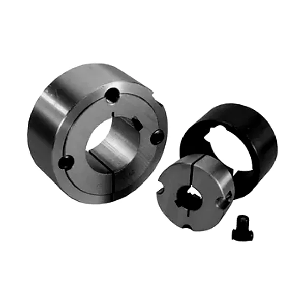
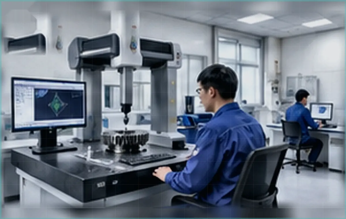
Machining visuals on this site illustrate the types of process stages relevant to a precision shaft interface: turning or boring, keyway and hole machining, deburring, cleaning and dimensional verification. They are composition/reference media, not published claims about a specific machine count or certified factory line.

Critical checks should follow the approved drawing and order: mating diameters or taper features, bore and keyway, thread condition, flange or shoulder faces, visible damage and any specified runout-related feature. If a documented inspection report is required, name the dimensions and drawing revision in the RFQ.
Send the component marking, shaft and keyway data, mating-part drawing or dimensions, photographs, duty and quantity. The more completely the interface is defined, the less likely a replacement is to be selected from appearance alone.
Need to compare families first? Use the product-family section above or contact engineering with the current drawing.
Bushings & Hubs engineering guide Use interface differences to make the choice Start this comparison task at nylon bushing; then use plain bushing to challenge the first assumption before tapered steel bushing is accepted. Treat nylon bushing, plain bushing and tapered steel bushing as separate compatibility gates. The preferred or interchangeable option is the one […]
Bushings & Hubs engineering guide Connect machine duty to mounting architecture The fastest route to a wrong answer is to let downtime cost stand in for standardization. This guide keeps spares, bushing family, and maintenance record visible until the decision is closed. Define the operating duty first, then connect downtime cost, standardization and spares to […]
Bushings & Hubs engineering guide Give Purchasing the Details Needed to Avoid Guesswork Instead of asking which part looks closest, prove replacement bushing and replacement hub on the machine, then decide how RFQ changes the installation or replacement path. Package replacement bushing, replacement hub, RFQ, the mating component and machine duty into one RFQ. Separate […]
The Blog menu is already configured. Technical articles are intentionally not published in this build phase, so the archive starts clean and can be populated later without changing the navigation system.
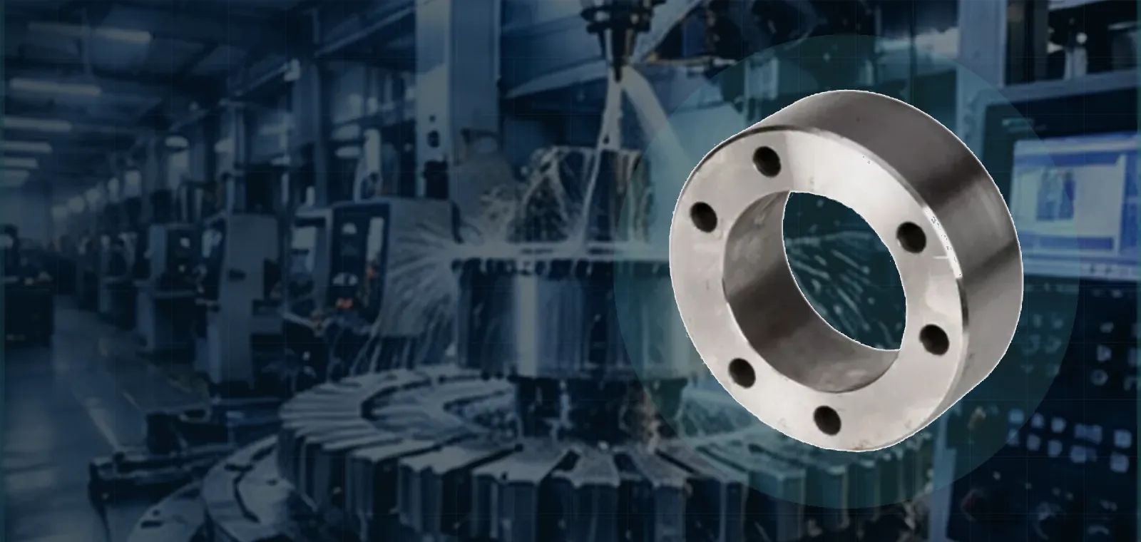
For an accurate bushing or hub match, send enough information to define the complete shaft-to-component interface rather than only a product photograph. The model marking is useful, but the shaft, keying, mating hub or mounted element, operating duty and inspection expectations are what make the selection reviewable.
When replacing a failed assembly, also include photographs of the shaft and mating surfaces after cleaning. We use those inputs to confirm the interface and identify missing questions rather than guessing from appearance.