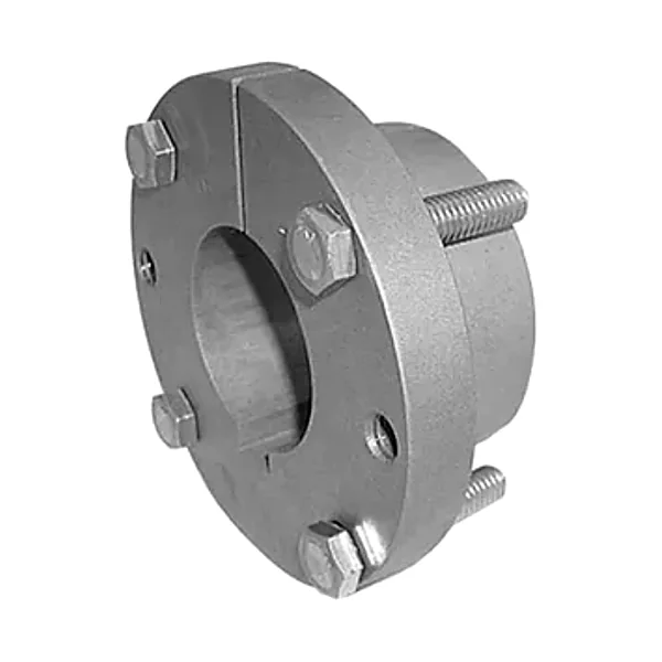
Description
Evidence-backed shaft mounting
XT Bushings
Select xt bushings by verified shaft, keyway and mating-interface data, with catalogue drawings available for engineering review.
What this product family covers
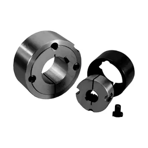
XT Bushings are presented here as an RFQ product family rather than a guessed one-size-fits-all component. The selected catalogue documents the series and mating geometry, while final bore, keyway and assembly details must be confirmed against the exact model and shaft. Published series in this family include XTB15, XTB20, XTB25, XTB30, XTB35, XTB40, XTB45, XTB50, XTB60, XTB70, XTB80, XTB100, XTB120.
The practical value of this page is to help engineering and purchasing teams identify the interface data that separates a correct part from a visually similar but incompatible one. The drawings and model lists are evidence-backed; operating limits, screw torque, finish, certification and lead time are deliberately left for project confirmation unless supplied in an approved drawing or order specification.
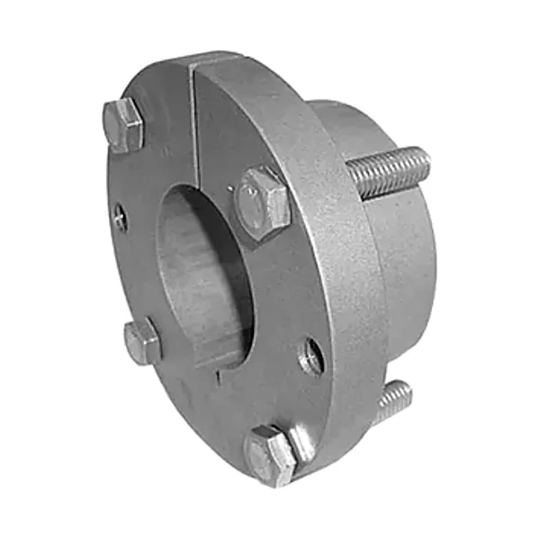
Structure and mating interface
The defining feature of this family is its XT tapered bushing with catalogued bore/keyseat options and cap screws. The interface converts screw tightening and taper or hub contact into a controlled mechanical connection. That makes surface condition and component matching important: a damaged taper, raised key, incorrect hub, paint on a mating surface or mixed series can prevent proper seating even when the bore nominally fits the shaft.
Selection starts with the interface, not with an outside diameter that merely looks similar. Record the shaft size and tolerance, key and keyseat geometry, the bushing or hub series printed on the existing component when available, the mating component geometry, and the assembly direction. Then compare those inputs with the correct series drawing. A taper system that appears close in a photograph can still use a different taper, flange thickness, screw pattern, keyway convention or hub seat.
For replacement work, measure after cleaning the shaft and mating part. Check for fretting, burrs, corrosion, bell-mouthed bores and key damage before assuming that the previous component failed because of the bushing itself. For new equipment, keep the shaft, bushing, hub and mounted element in one drawing stack so concentricity, axial location and service access are considered together.
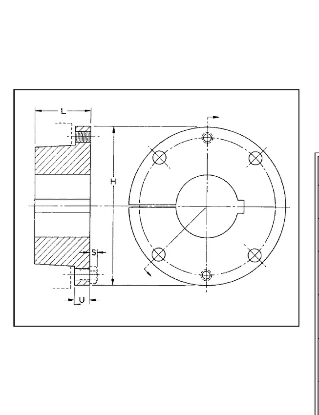
Dimension drawing before specification
Use the drawing as the geometry checkpoint before reading or requesting a model-specific table. Dimensions must be taken from the selected series and bore, not extrapolated from this page.
Specification and RFQ fields
| Selection field | Published family information | Engineering check |
|---|---|---|
| Series / model group | XTB15, XTB20, XTB25, XTB30, XTB35, XTB40, XTB45, XTB50, XTB60, XTB70, XTB80, XTB100, XTB120 | Match the identifier and mating family before checking dimensions. |
| Mounting interface | XT tapered bushing with catalogued bore/keyseat options and cap screws | Confirm shaft, key/keyseat, taper or hub seat and fastener pattern. |
| Bore & keyway | Catalogue-controlled by series | State exact bore and keyway in the RFQ; do not infer from nominal product name. |
| Duty data | Project-specific | Provide speed, torque or transmitted load, duty cycle, shock, environment and alignment conditions. |
| Material / finish | Confirm by selected part/drawing | Do not assume a material or coating from product color alone. |
Application solutions and duty context
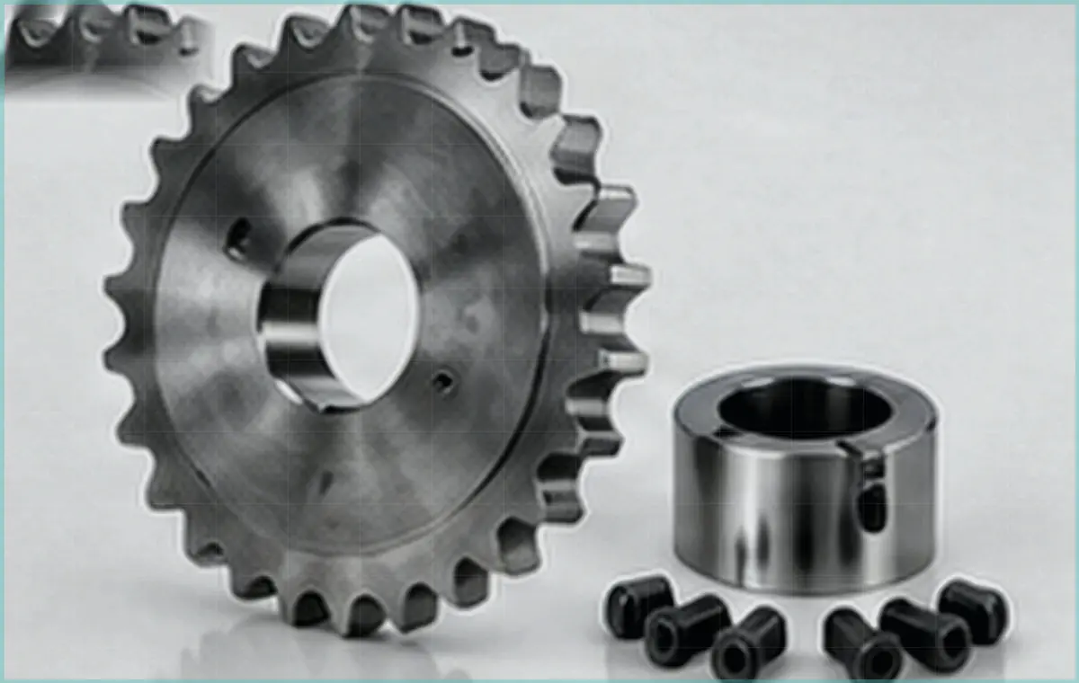
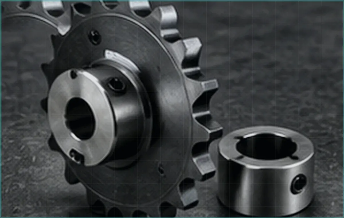
The catalogue family is relevant where a removable shaft-to-component connection is needed in conveyor pulley and large rotating equipment mounting where XT geometry is specified. In a pulley or sprocket drive, the bushing/hub decision is part of the full rotating interface: shaft size, keying, axial location, overhung load, alignment and service access all matter. A product family should therefore be selected with the mating component, not independently.
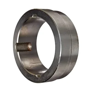
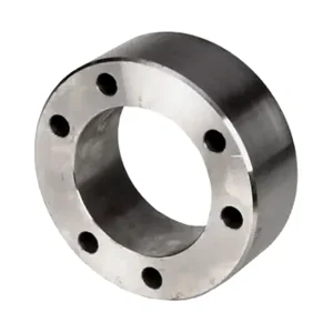
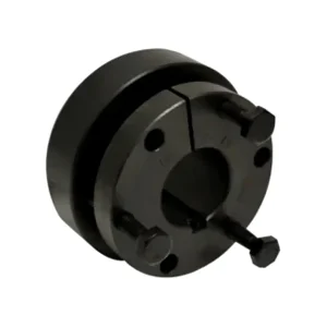
For fabricated assemblies, give the hub or plate drawing and weld/bolt arrangement so the connection can be reviewed without assuming that a standard photograph represents the final construction. For replacement work, include photographs only as supporting evidence and pair them with measurements; photographs are especially useful for confirming flange style, split direction and screw placement but are not a substitute for dimensions.
Selection and customization workflow
Selection starts with the interface, not with an outside diameter that merely looks similar. Record the shaft size and tolerance, key and keyseat geometry, the bushing or hub series printed on the existing component when available, the mating component geometry, and the assembly direction. Then compare those inputs with the correct series drawing. A taper system that appears close in a photograph can still use a different taper, flange thickness, screw pattern, keyway convention or hub seat.
For replacement work, measure after cleaning the shaft and mating part. Check for fretting, burrs, corrosion, bell-mouthed bores and key damage before assuming that the previous component failed because of the bushing itself. For new equipment, keep the shaft, bushing, hub and mounted element in one drawing stack so concentricity, axial location and service access are considered together.

Installation, removal and commissioning
Installation should follow the drawing and instructions for the exact series being fitted. Clean mating surfaces, verify that the key does not hold the assembly off its taper, and tighten fasteners progressively in the specified sequence. Do not substitute a generic torque copied from a different bushing family; fastener size, material, lubrication state and series geometry change the required value. After the first loaded run, inspect for movement, unusual heat, loose hardware, fretting dust or runout.
Removal should use the designed release feature when the series provides one. Avoid hammering on a finished bore or cutting close to the shaft unless a controlled repair procedure has been approved. If a hub or shaft shows damage, treat the mating component as part of the root-cause review rather than installing a new bushing into an unverified seat.
Inspection and maintenance
Routine inspection is mostly visual and dimensional: confirm axial position marks have not shifted, fasteners remain secure, the mounted element runs without new wobble, and there is no rust line or dark debris indicating relative movement. In dusty, wet or wash-down service, include the interface in the normal corrosion and contamination review. When vibration changes, inspect the complete rotating stack because shaft straightness, key fit, bearing condition and mounted-component balance can all produce symptoms at the bushing.
Keep an asset record with the installed series, bore, keyway, shaft location and associated drawing. That record is more useful than a generic description such as “taper bush,” and it shortens future maintenance because the replacement can be checked against a known interface before shutdown.

Manufacturing and quality-control questions
Manufacturing and inspection should focus on the features that control fit: bore and keyway geometry, taper or mating diameter, flange and shoulder faces, fastener threads, runout-related surfaces and visual condition. The site uses machining and metrology imagery as workflow illustrations only; those images are not presented as proof of a particular machine count, certification or factory line.
For an order that needs documented inspection, specify which dimensions require a report, what drawing revision applies, and whether material or coating documents are needed. This prevents a generic “quality certificate” request from being interpreted differently by engineering and purchasing teams.

Frequently asked questions
How do I choose the correct xt bushings series?
Start with the series identifier and mating component, then verify shaft bore, key/keyseat, taper or hub geometry, fastener pattern and assembly direction against the corresponding drawing.
Can I replace one taper or QD family with another if the bore is the same?
Not safely by bore alone. Different families can use different tapers, flange dimensions, fastener patterns and hub geometry. Treat interchangeability as a drawing-level question.
What information should I send for a replacement?
Send the existing series/model marking, shaft diameter and tolerance, keyway dimensions, mating component drawing or measured interface, photographs, duty, environment and quantity.
Do you publish a generic tightening torque on this page?
No. The correct tightening value depends on the exact bushing family, fastener and approved instructions. Use the value specified for the selected component rather than a generic number.
What should be inspected after installation?
Check axial position, runout or wobble, fastener security, unusual heat, fretting debris and any change in vibration after the assembly has been loaded.
Can the product be customized?
Drawing-based configuration can be reviewed when standard catalogue geometry does not match. Provide the mating interface and operating requirements so any deviation is explicit and reviewable.
Related engineering paths
Use related pages to compare an interface decision, not to treat visually similar systems as substitutes. For a wider comparison of mounting systems, see the Bushings & Hubs selection page. If your assembly uses a fabricated plate or wheel, compare the weld-on hub families and check how the hub is integrated before selecting a bore. For a quick-detachable interface with a different mating system, review Standard QD Bushings. Keep the shaft drawing, mating component and exact series together during comparison so a navigation shortcut never becomes an interchangeability assumption.
Prepare a useful RFQ
For an accurate bushing or hub match, send enough information to define the complete shaft-to-component interface rather than only a product photograph. The model marking is useful, but the shaft, keying, mating hub or mounted element, operating duty and inspection expectations are what make the selection reviewable.
- Shaft diameter and tolerance, plus keyway or spline details.
- Mating pulley, sprocket, hub or fabricated-component drawing and the required series if known.
- Speed, transmitted load or torque, duty cycle, shock, environment and service-access constraints.
- Quantity and any material, finish, marking or documented-inspection requirement that must be confirmed.
When replacing a failed assembly, also include photographs of the shaft and mating surfaces after cleaning. We use those inputs to confirm the interface and identify missing questions rather than guessing from appearance.
Failure review and replacement discipline
When a bushing or hub is being replaced after loosening, cracking, fretting or repeated runout, record the condition before disassembly. Look for witness marks, polished taper zones, displaced keys, thread damage, corrosion, uneven contact and evidence that the mounted component has shifted axially. These observations help separate a component problem from alignment, fit, assembly or duty issues. Replacing a visibly damaged part without correcting the mating shaft, hub or installation condition can reproduce the same failure.
For root-cause review, retain the old part long enough to compare its bore, keyway, taper and flange against the intended drawing. Confirm that the installed family actually matches the mating hub and that the shaft has not been repaired or modified outside the original specification. Where a drive has recently changed speed, load, pulley diameter or machine duty, include that change in the RFQ so engineering can review the interface in context.
Receiving, storage and spare-parts identification
At receiving, verify the series/model, bore, keyway, mating fastener set and visible finish before the component is released to maintenance. Store matched screws with the bushing family rather than in a general fastener bin, and protect precision bores, tapers and seating faces from impact and corrosion. If several similar families are stocked, use a bin label that includes both the series and bore instead of relying on outside diameter or color.
For critical spares, keep the drawing or catalogue reference with the stock record and note which machine assembly uses the part. This makes future replacement faster while reducing the risk of mixing visually similar QD, taper-lock, split-taper or XT interfaces that may share a nominal shaft size but differ in geometry.